One of the best running N scale layouts I’ve operated on uses under the table slide switches for turnout control. It inspired me to do the same on my “New NCR” layout. This is how I do it.
I started doing some research on the methods that people use and came across the great article Bill Denton wrote in the July/August 2007 edition of N Scale Magazine. This article covers how Bill handles turnout control on his legendary Kingsbury Branch layout.
He used DPDT slide switches and RC aircraft control lines to perform the three vital turnout control tasks: holding the points of the switch in the correct position, switching the polarity of the electricity fed to the frog, and providing a method for operators to throw the switch. His approach worked great and I wanted to replicate it.
However, because it was 2021 when I first started working on the project, and I knew I had a decent number to install, I wanted to design a solution that not only functioned well but that was also easy to source, assemble and install.
Like the “Kingsbury Method”, my approach is to use a DPDT slide switch to provide the power routing and locking and similar RC hardware connected to fascia mounted knobs to actuate them. Unlike Bill’s approach I’m using 3D printed brackets to hold the slide switches in place.

But before I could design that bracket I started by sourcing materials.
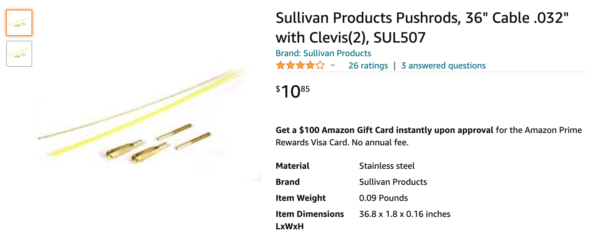
The control rod was easy. It’s the same thing Bill used: Sullivan Products Gold-N-Rod.
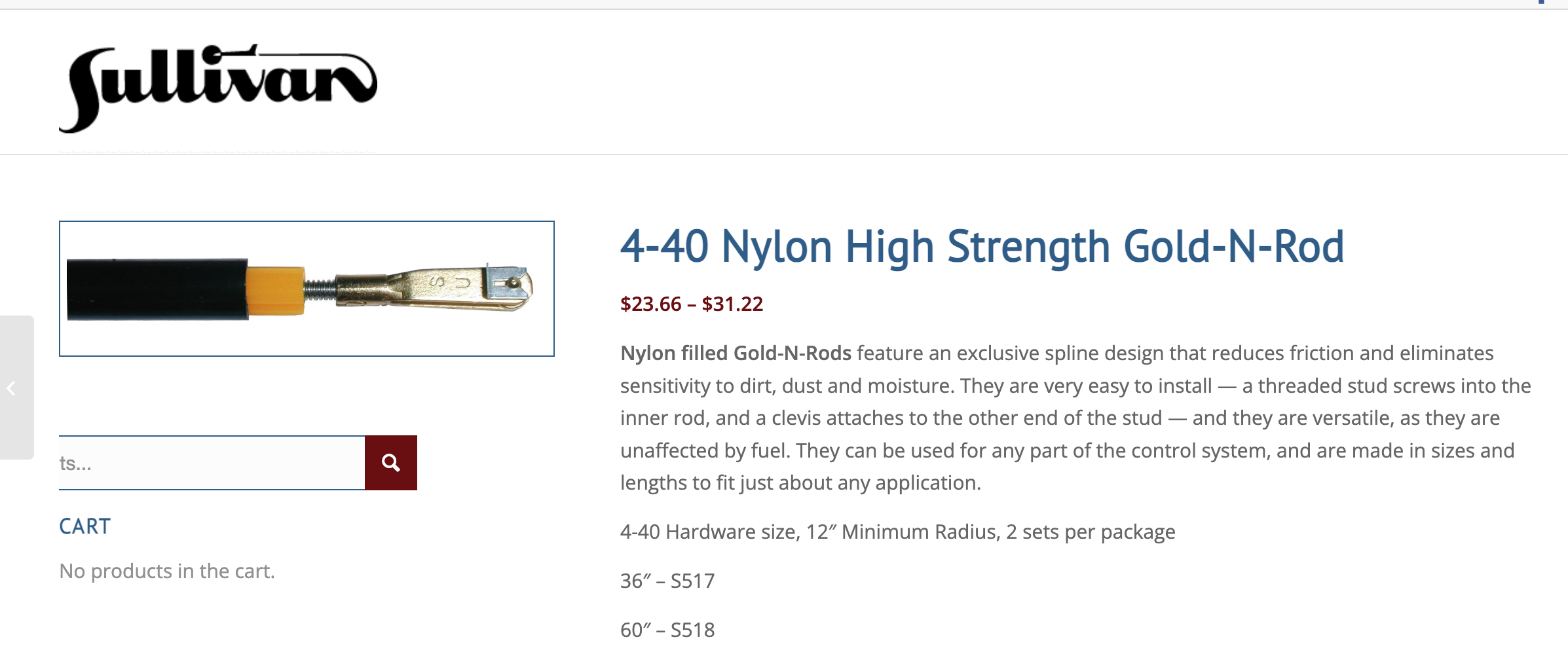
It is, unsurprisingly, available through Amazon too. You’ll notice a theme when it comes to that…
The Gold-N-Rod is held under the layout with cable clamps. I’m using these.

I wanted some good “industrial” looking knobs for control and, after doing a lot of browsing around the internet, I found ones I liked on Amazon. While Bill’s original approach uses other pulls, I was seduced by the wide availability of draw/cabinet pulls for this purpose. Look around and you’ll likely find something you like too. Don’t worry about the mounting method (as long as they take a single screw) since I have a solution for joining the rod to the knobs.

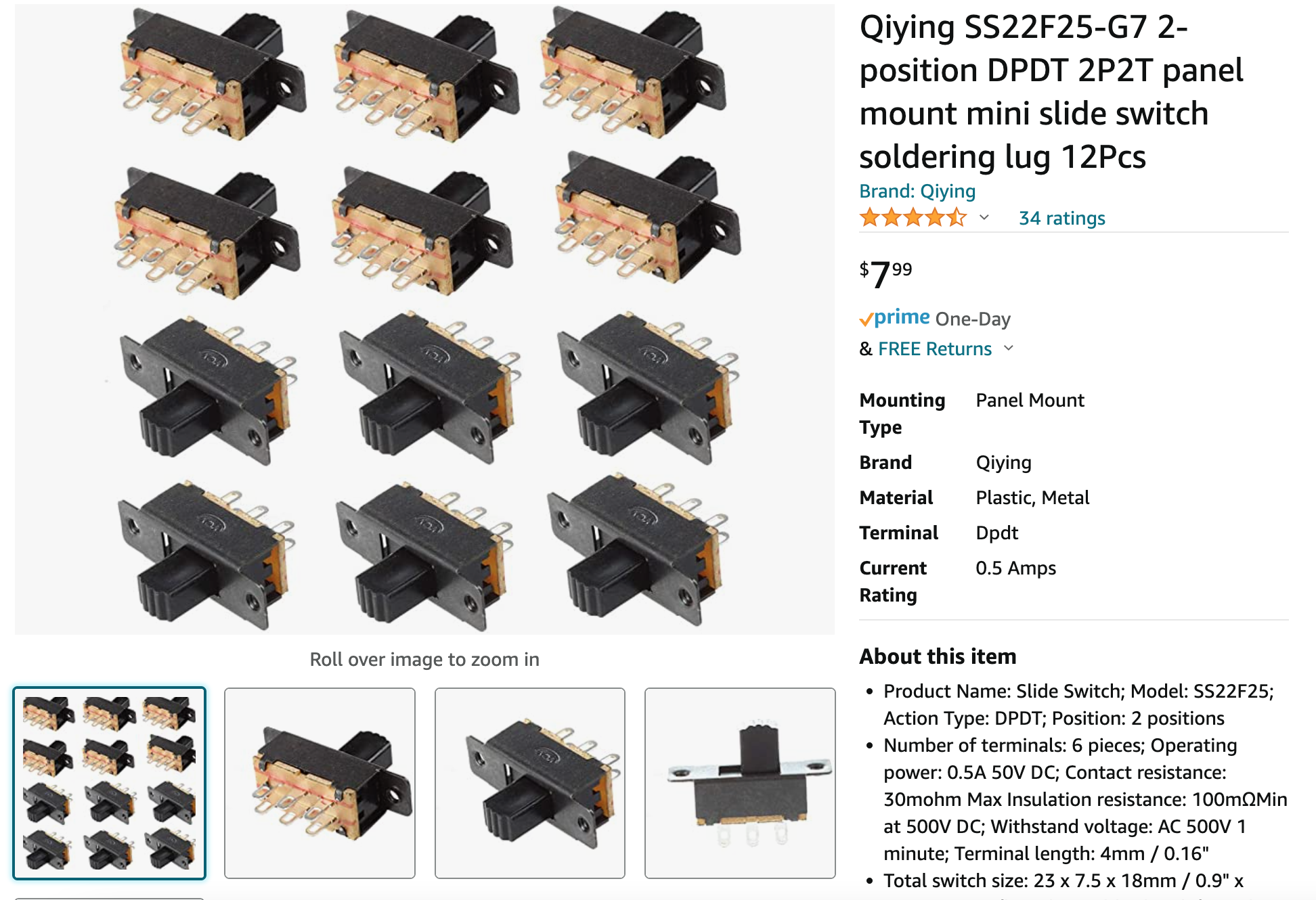
Then it was onto the slide switches. So far I have been using the “Qiying SS22F25-G7” that I found on Amazon. I’m not in love with them, but they’re what you’ll see for now.
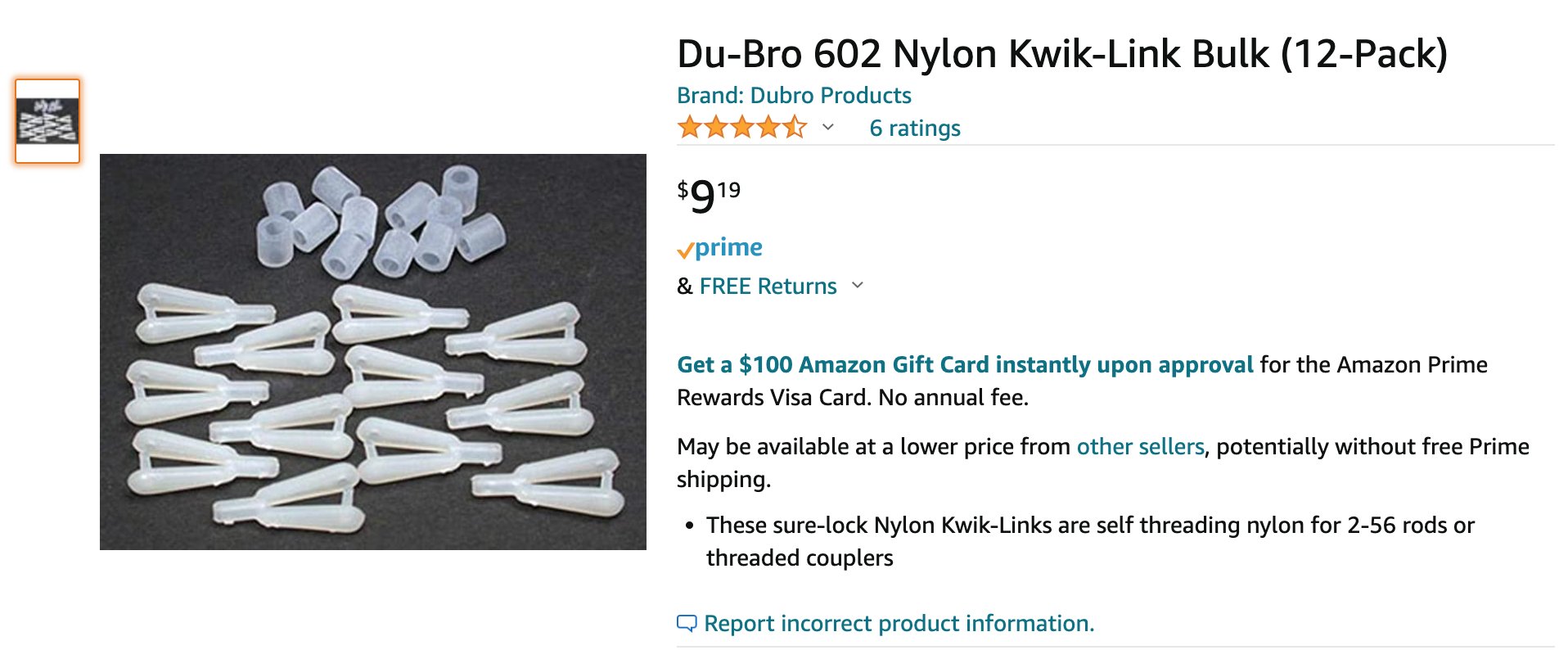
I attach the Gold-N-Rod to the slide switches using nylon “Kwik-Link”s from Du-Bro.
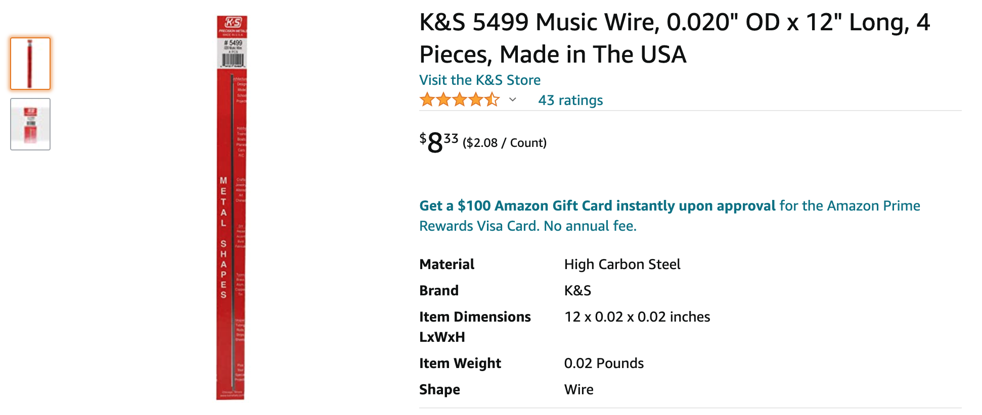
I use some music wire to throw the turnouts themselves. K&S .020 music wire does the job for me.
You’re gonna need some screws, of course, and I use both some 2-56 screws to attach the switches to the mounts and some 1/2″ wood screws to stick everything to the layout.


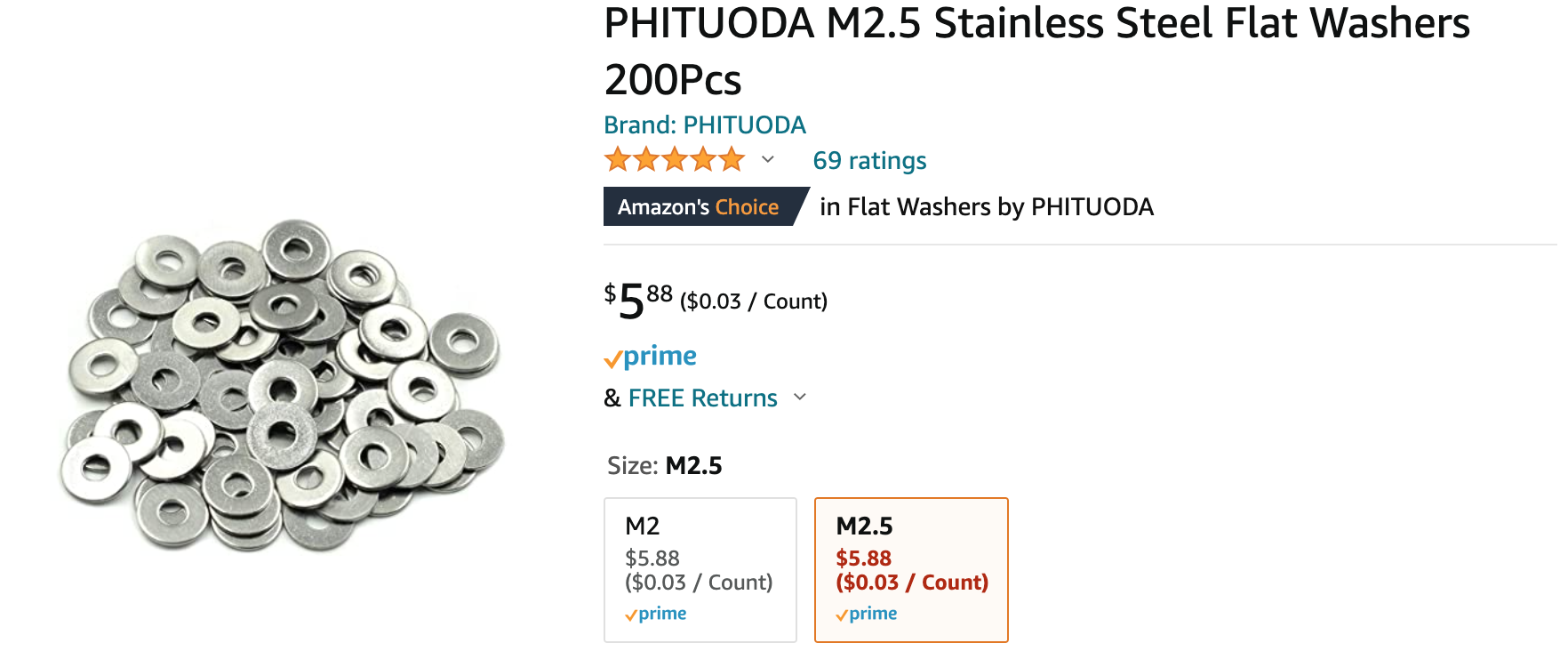
Along with those screws, I use some 2-56 washers to account for slop in the mounts.
Here’s a consolidated bill of materials:
- Sullivan Products Gold-N-Rod nylon control rod
- Cable clamps
- Qiying DPDT slide switches
- Throw knobs
- Du-Bro Nylon Kwik Links
- K&S .020 Music Wire
- 2-56 Screws
- 2-56 (M2.5) Washers
- #6 x 1/2″ Wood screws
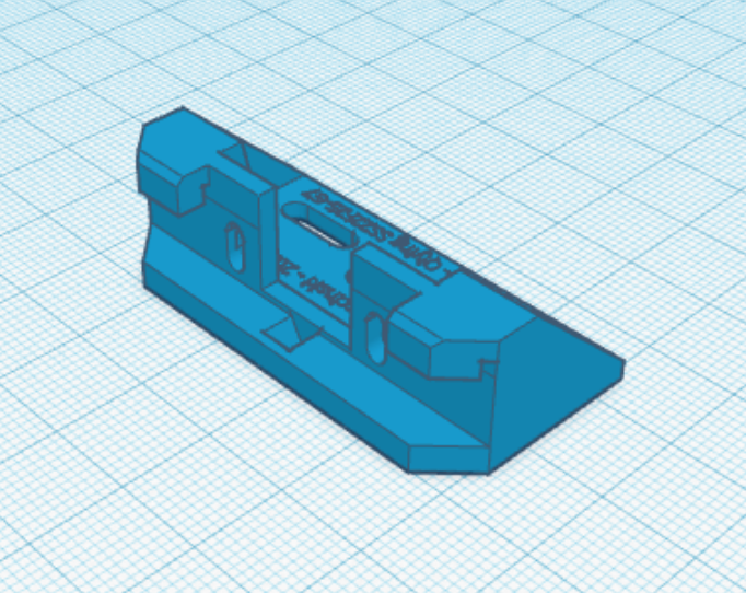
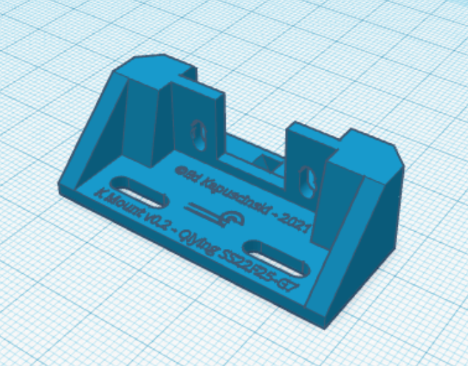
Now lets talk about those brackets.
I wanted something with adjustability built in and a solution to hold the throw wire (that runs up to the turnout throw bar), so I designed “The Kingsbury Mount” in Tinkercad. The mount also provides a fulcrum so that the slide switch’s throw is magnified and can provide enough holding force to keep the turnout aligned.
Originally I had a friend print me a bunch in exchange for some beer, but now that I have my own FDM printer, there’s no stopping me.
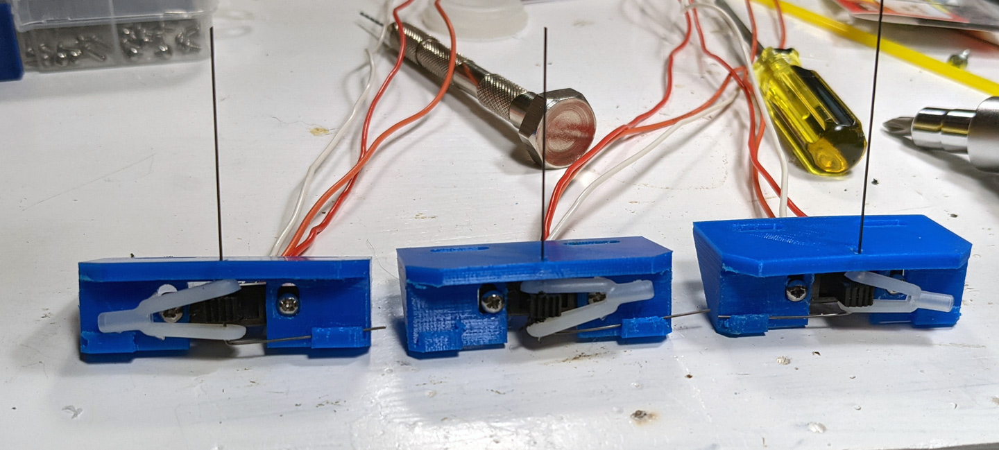
I pre-assemble mounts with switches on the workbench, then attach them under the layout. Lastly I hook everything up with the linkages knobs and wiring.
Before assembly begins some part prep must be performed on the Kwik-Links and slide switches. I first clip the “posts” that connect one side of the “yoke” to the other. Then I drill a hole through the clipped side so that a wire can easily pass through. Use a drill bit the corresponds to the existing hole size on the other side of the yoke for convenience. Next, use that same drill bit to drill through the center of the slide switch’s switch nub. You’ll find that this hole will be considerably larger than the wire that will be going through it, but that slop is both intentional and required.
Throw wires will need to be bent to actually actuate the turnouts. Originally I bent these into a simple L shape that was long enough to reach through the layout and into the throw bar on one side and just long enough to engage the small “lip” that protrudes to retain it on the mounts. After some experimentation, I found that the entire thing works even better if you shape the part that catches on the lip more like an inverted checkmark. This provides some additional tension to hold the whole thing together.
It’s best to solder leads to the DPDT switches prior to assembly as well. Since I don’t need both poles of the switches I connect my leads to both of them. This is good because you the contacts can fail and you get some redundancy by connecting the wire to both of them. I had, for a long time, followed a consistent wire color scheme that uses red for one polarity, white for the other, and orange to the output (center pole). In retrospect I should’ve chosen colors that would be a bit more easily distinguished in the darkness under the layout. The red and white are ok, but sometimes it’s tough to pick out the red from the orange.
If you’re smarter than I am, you’ll be better at planning the orientation for the slide switch so that the wire colors all match up with your bus wires appropriately, but so far I’ve been hit or miss on this.
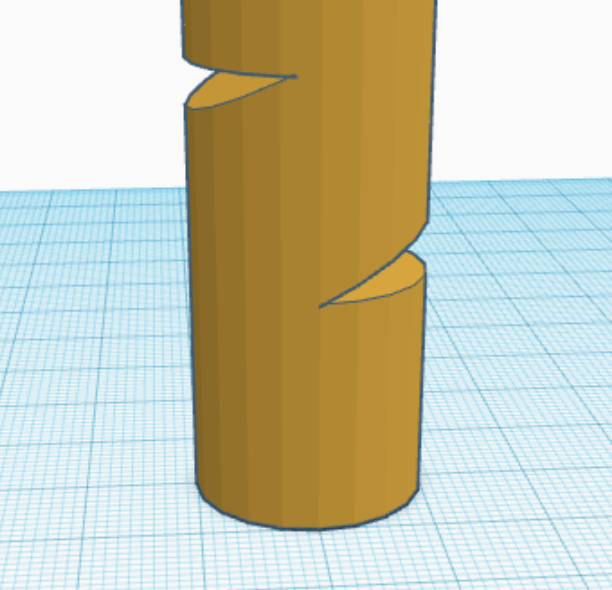
The last pre-assembly that you’ll want to do is in attaching the knobs to the Gold-N-Rod. You’ll notice that the threads inside your knobs almost certainly do not match up with the 2-56 hole in the rod. That’s totally ok though. I have found that glue does a perfectly acceptable job of holding the rod to the knobs. I cut short (~1″ lengths) of the rod and place small nicks in the end of it with a knife like in the illustration.
Next, some CA glue is put down into the hole in the knob and the rod is inserted in. Once the glue dries you’ll have a nice hard interlock between the rod and the threads in the knob. This means that in order to pull it out the CA will need to be crushed which will be nearly impossible. These knobs can now be joined to the main throw rods with the threaded couplings.

K-Mount assembly is done by using the 2-56 screws to attach the slide switches to the mounts. Then slide a Kwik-Link around the slide switch nub and pass the actuation wire through it. Clip the other end of the actuation wire’s L shape into the lip on the mount, and you’re ready to attach everything to the layout.
Mounting is as easy as assembly. Drill a hole under the holes in the throw bar on the turnout you’re going to control. Pass the actuation wire up into the hole in the throw bar and align the mount perpendicular to the track. Get everything roughly lined up then drive in two wood screws roughly in the middle of the slots in the mounts provided for that purpose. Because they are slots as opposed to simple holes you’re able to get everything nicely lined up before tightening the screws.
The Gold-N-Rod that runs to the fascia is connected to the Kwik-Link using a 2-56 threaded coupling. Use the cable clamps to secure the rod (inside its red sleeve). This is important to ensure that things stay lined up when an operator pushes or pulls the knob. Lastly the knob and short Gold-N-Rod is attached using another threaded coupling.