Empowered by my recent progress on the one end loop I bit the bullet and started on the next one. It was even more complicated to build, but I can happily report that it is now up and running! At the same time I also purchased a large format printer for future backdrop prints, which were my next big hurdle in getting scenery started.
First, the loop. This one is at the north end of the layout and takes the place of where the staging yards will be in the future. It was a challenge due to being located in the laundry room, where space is tight and there are lots of things I need to keep it out of the way of (like two electrical boxes: thanks weird house).
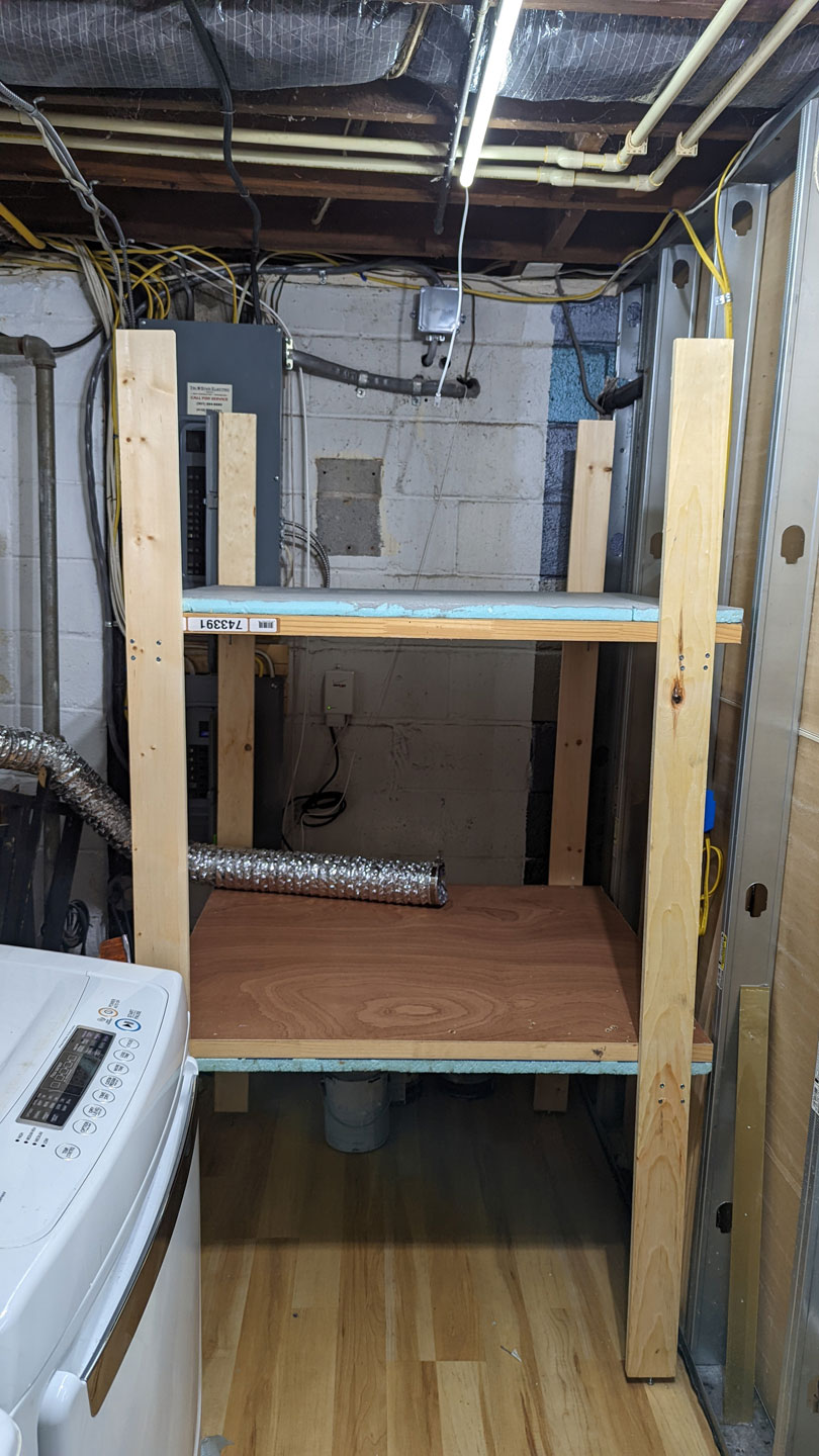
I built a double shelf setup reusing one of the doors from the Coal Country layout cut in half. The top shelf is for the layout, the bottom is for the 3D printers (hence the exhaust duct). I KNEW assembling this all in place was going to be a struggle since I can’t get to the back of it, and can’t pull it out further (due to the dryer).
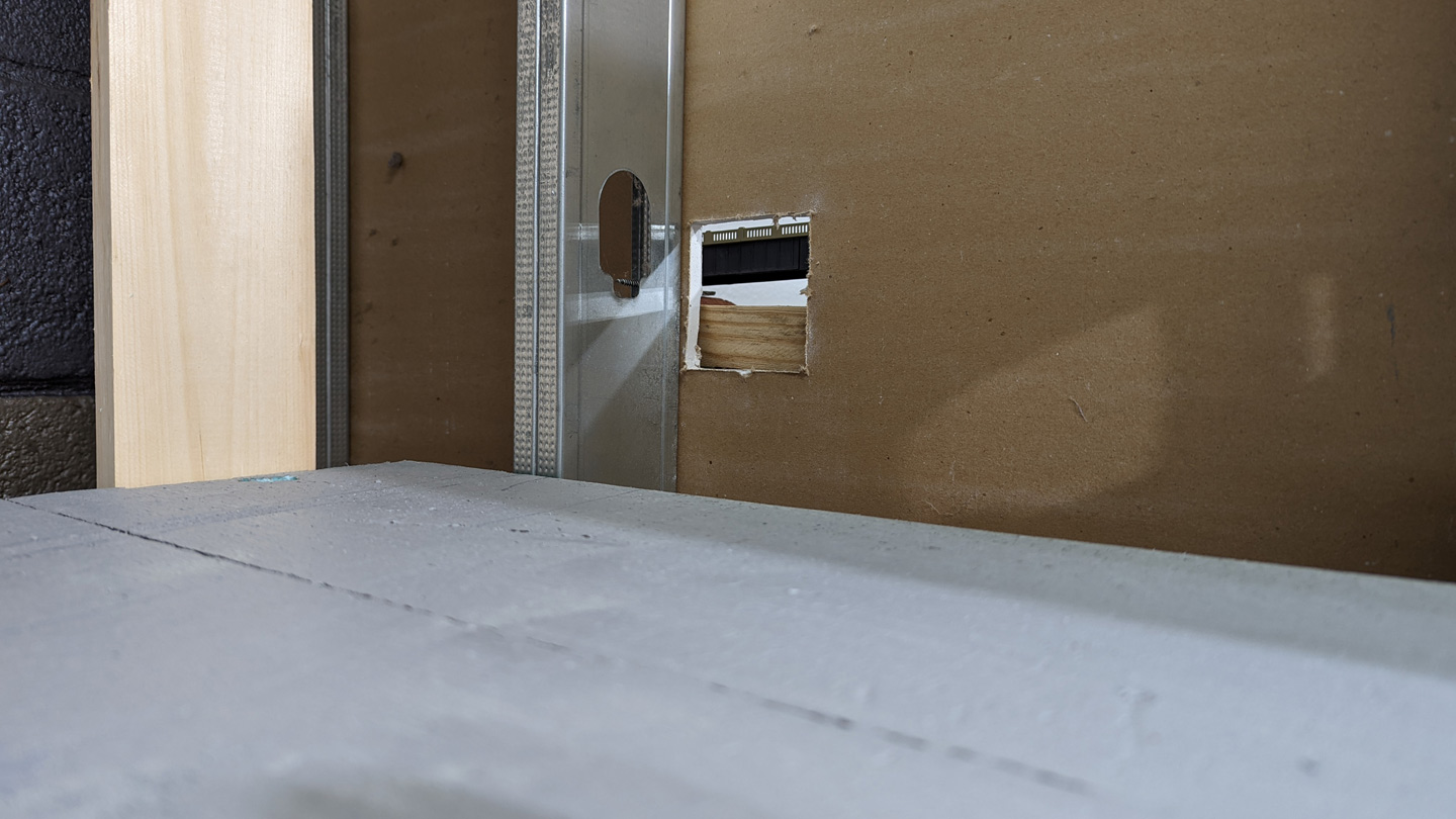
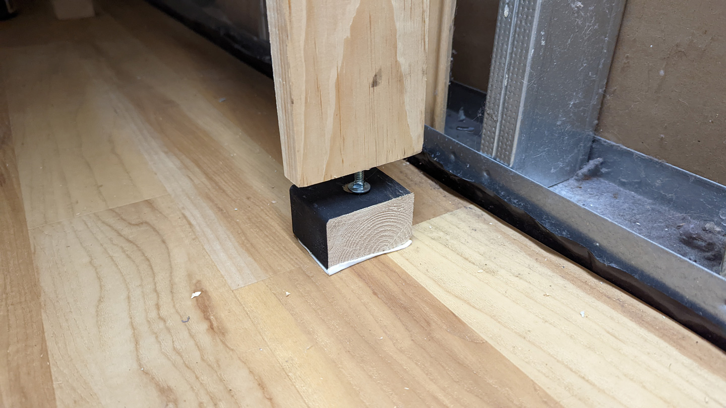
I needed a way to bring it into the room in parts and then assemble it in place. I am pretty proud of my solution for this. I added blocks to the uprights that would support the deck at the right height. These were assembled in the workshop. I then and drilled a hole through them and a corresponding hole through the deck for a 6″ 1/4-20 bolt.
When it was time for assembly I propped the uprights up against the wall and dropped a bolt through the hole in the deck. I was then able to maneuver the bolts into the holes in the blocks and boom: everything was lined up and in place enough that I could then (with the help of my wife) tighten a nut onto the bolt to hold everything fast. It’s not the most secure mounting, but it worked well enough and with some bracing everything works just fine. If additional rigidity is needed, I can always now sink some wood screws through the uprights and into the deck, but it hasn’t seemed necessary.
You can see in the photo that I also employed “NTRAK style” adjustment bolts on the bottom of the legs. This was absolutely neccessary because nothing in my house seems to be flat, square or plumb. This space was especially challenging because there is a slope to the sump in the floor. T-Nuts and bolts solved the problem for me without having to pre-engineer in precision.
One of the key dimensions of this construction was getting the deck level with the layout in the other room. I made sure to measure twice, right?

But when it came time for assembly… uh oh.
I don’t know how I screwed THAT up, but I’m guessing it had to do with my double counting the height of the blocks that the decks sit on. I was pretty pissed at myself for this given how tough it was maneuvering things in the space. I did NOT want to knock the whole thing down and reassemble it again (I don’t think my back would’ve signed off on that). It’s a good thing I have friends I can complain to about my struggles though. My friend Dave Foxx said something like “just put some blocks under the legs and JFRTM”. So… that’s what I did!
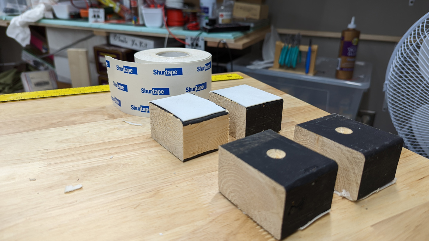
I put a little more engineering into them though to keep things from getting crazy. I used a countersink bit to put divets in them for the leveling bolts to sit in and added some Shurtape to the bottom so prevent them from sliding around. They worked like a charm.
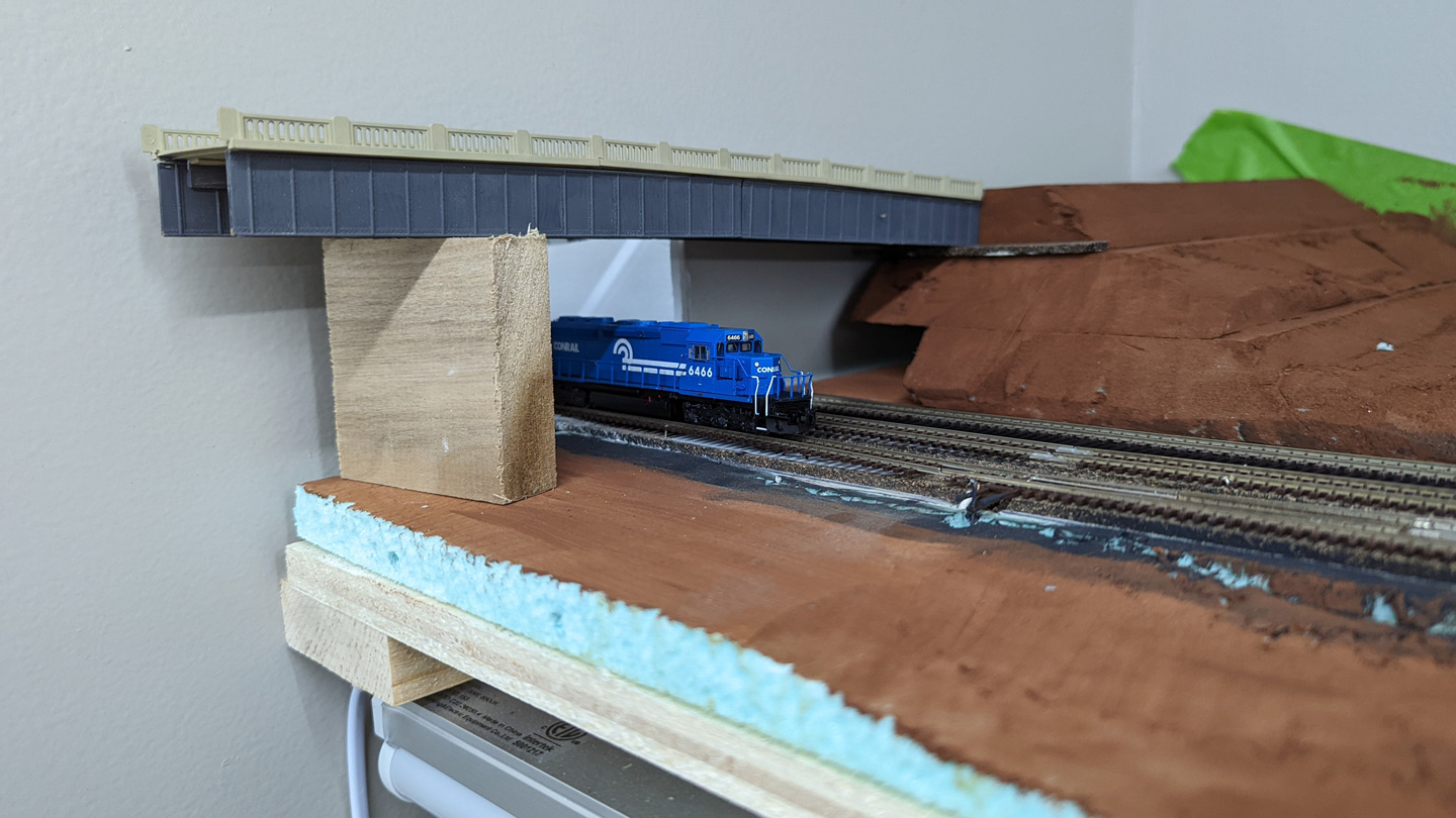
Now onto the next challenge. Bridging the gap. 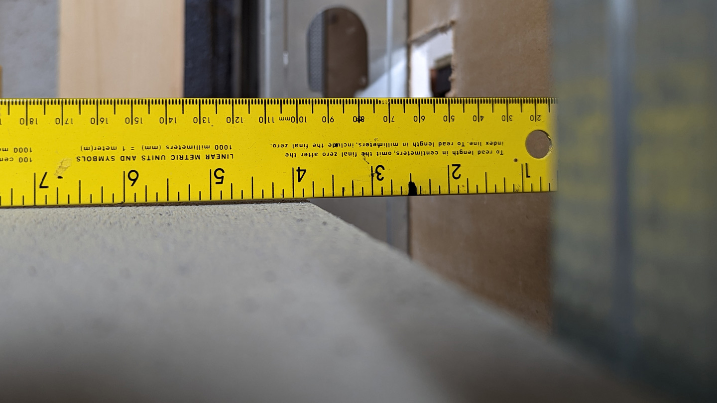
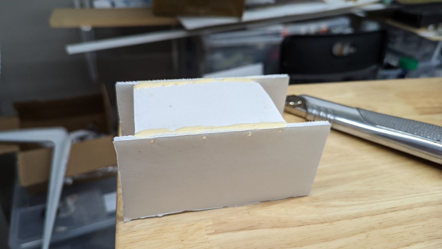
My old friend foamcore came to the rescue! I designed and built a “bridge” that drops into place. The walls keep trains from falling off and provide structural rigidity. It was assembled with wood glue and, most importantly, pins from the side into the deck. It won’t span the grand canyon, but hopefully it’ll work just fine for the year that it needs to exist.
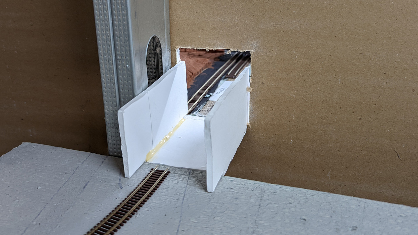
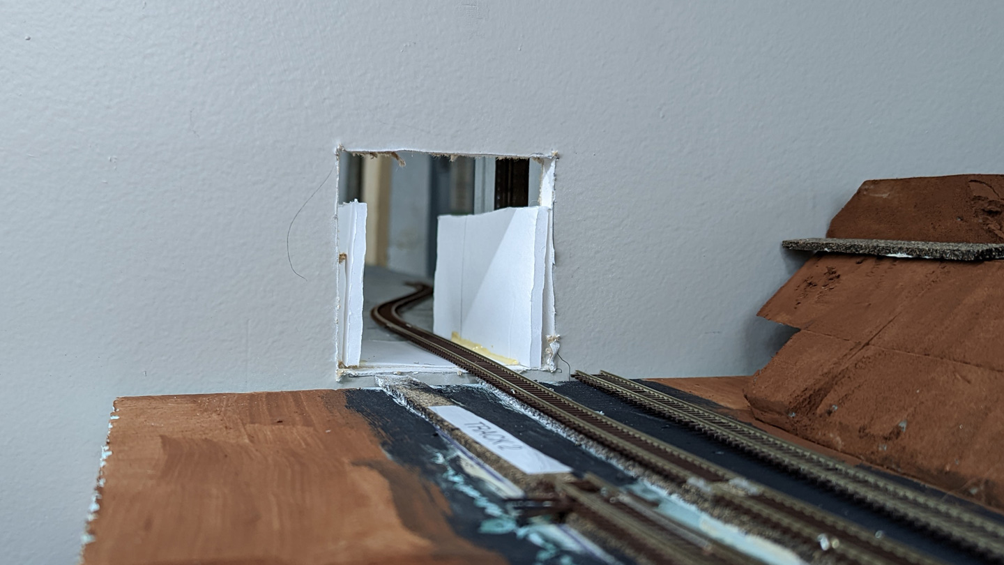
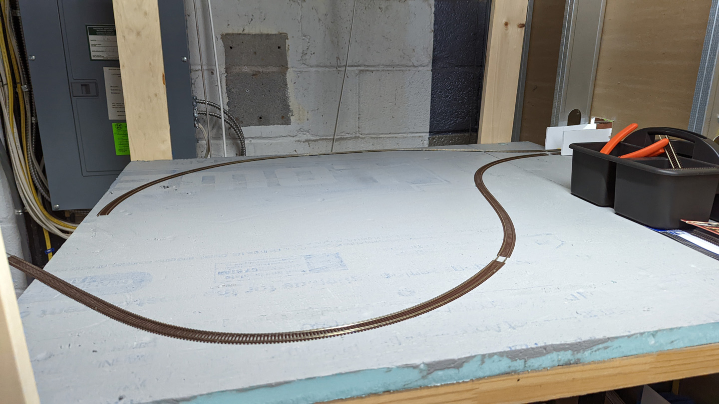
So now I had everything in place to allow track to proceed from CP Loucks back into itself. Laying track beyond your reach is always a challenge. In this case I used snap track to get reliable radii and made assemblies that stretched my entire “unreachable” area. I was then able to easily join things up on the visible layout where I could see (as you can see in the photo above).

After getting the one end in place I started on the other end of the loop. Things were going relatively well here.
But then, just when it was going to be golden spike time… disaster.
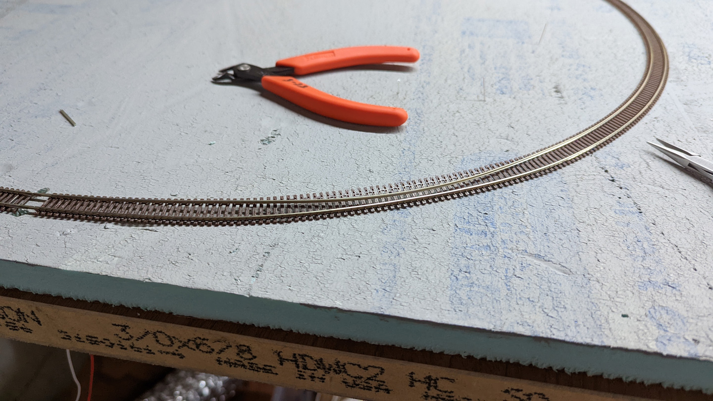
I believe that I heated the rail up too much while using a Dremel to cut it to size, which weakened the spike heads, and caused the “Penn Central Golden Spike”. I swapped out the piece of track (and taped a note on the removed and repaired piece that it was for “straight use only”) and was back in business.
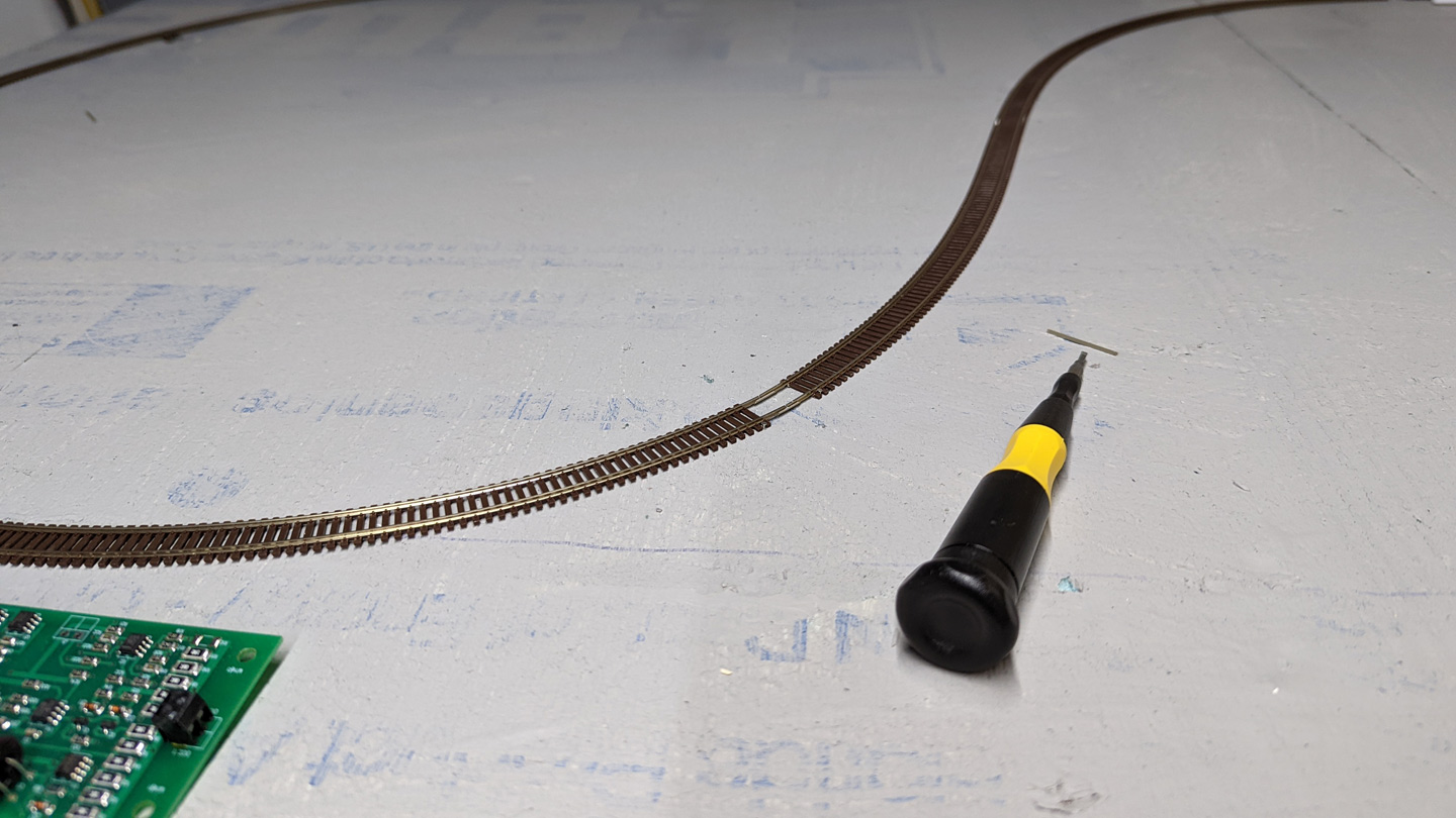
Are joints in the middle of curves bad news? Yes. But what ya gonna do?
Visible also is the DCC specialties OG-AR that I’m using for auto reversing (it’s salvaged from my past NCR layout and on loan from the DCC In a Box box). I was hoping to be able to use it inline with one of my Digitrax BXP88 outputs so that the loop could be detected mainline trackage. Turns out that you cannot use an OG-AR like this as will always show the block as occupied. I’ve had some helpful suggestions from friends about how to do detection + reversing, but given the temporary nature of this rig, I’m not really worried about it.
So, with track in and power applied, it was time to test it out!

Departing CP LOUCKS at Track 1.

Around the loop.
And back to whence we came on Track 2.
There is still much to be done on this rig to make adjustments to the track and improve reliability, but it’s great progress that I’m very excited about.
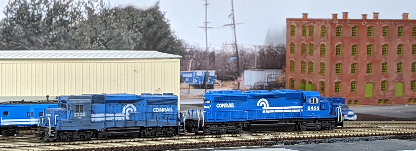
And, as promised… a bonus photo with a quick test using my new backdrop printer.